
Threading the 69kV to 161kV Needle

Carroll Electric Cooperative Corporation (CECC) engaged Allgeier, Martin and Associates to redesign an existing 69 kV line in northwest Arkansas for future operation at 161 kV.
Challenges
This particular line offered several challenges in design. The existing widths of Right-of-Way (ROW) varied from parcel to parcel. However, a significant portion of the ROW was 25 feet on either side of the centerline, for a total ROW width of 50 feet. The Razorback Regional Greenway trail was constructed under a portion of the line weaving in and out of existing poles. A four-lane road had been built around a portion of the line with existing poles now located in a median. There was a crossing of a golf course and Interstate 49, an existing double-circuit underbuild currently serving the local community, extensive underground facilities in the area, and many others. Landowners have constructed homes, businesses, utilities, and road improvements in the vicinity of the poles and lines since they were constructed decades ago. Because of this, the team determined new poles should be put back near the locations of the existing poles.
Specifications
CECC’s lines are designed to meet the specifications of the National Electrical Safety Code and the Rural Utilities Service (RUS). The required vertical clearances are typically obtained by increasing the structure height, while horizontal clearances typically depend on the structure framing, voltage, width of right-of-way, and conductor properties. Horizontal clearances must be met for two conditions: the conductors at rest (i.e. no wind), and when displaced by a wind blowing across them.
RUS provides guidance in selecting the ROW width for overhead transmission. The necessary ROW width is primarily a function of the distance the conductors are attached to the structure from the center of the ROW, the amount of conductor blow out, how much a structure deflects in the wind, and the required electrical clearances. The amount a conductor blows out will increase as the span length increases for a given conductor tension. Therefore, maximum span lengths can be calculated for various pole framings and ROW widths.
““The conductor needed to thread the needle.””
Options
Numerous options were considered for the redesign. Underground transmission, traditional overhead delta framing, and vertical tangents with offset poles each had appealing aspects but did not satisfy the project needs. Reconstructing using underground transmission utilized material that is non-standard to CECC’s inventory and construction practices at a higher cost. Underground transmission increased the potential of dig-ins in an area that is under heavy commercial development. Traditional overhead framing would require additional ROW to be obtained to allow for the conductor blowout for a significant number of spans. Several residences and businesses were located at or near the edge of the ROW and would require relocation or modifications. Other options had to be explored.
A typical solution often utilized for narrow ROW is to use vertical framing with the conductors all on one side of the pole. The pole is then offset to keep the conductors in the center of the ROW. This method would work for a portion of the line, but due to the Razorback Regional Greenway trail, poles in the median, underground utilities and distribution underbuild constraints this could not work for the entire line. In these areas the conductor needed to be in the center of the ROW and the poles needed to go back near the same location as the existing poles. Essentially the conductor needed to thread the needle.
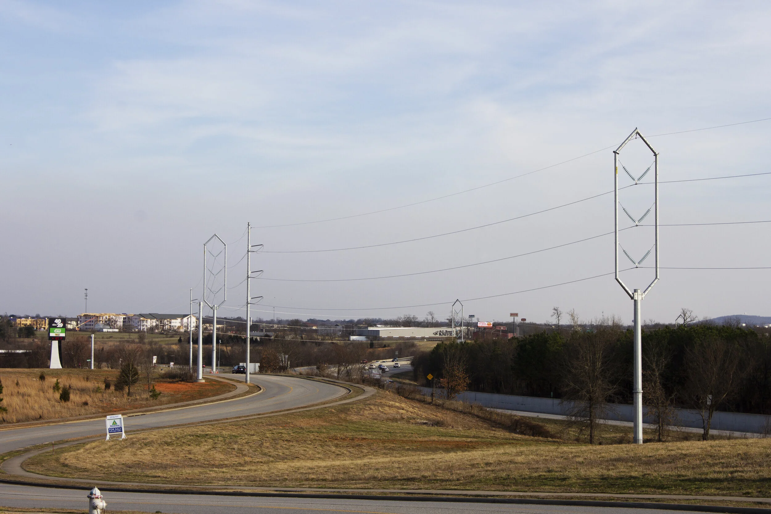
Needle Structure Innovation
Hence, the needle structure was conceived as a way to accommodate the conductor in the middle of the structure while also allowing for the pole base to be put back in the same location. The structure geometry was determined for a symmetrical structure allowing for proper phase-to-phase clearances as well as clearances for the conductors to structure surfaces. Toughened glass V-string insulators were selected to essentially fix the conductor location at the structure attachment, provide additional weight and enhance the aesthetics.


A conceptual design was modeled using PLS software. Various loading conditions were analyzed to determine the required member sizing and properties. Since the span lengths and angles did not vary greatly on the tangent structures on the project, the same pole top was used for each structure while varying the base to increase or decrease the height. This reduced the time required for detailing, drafting, reviewing, and simplified construction.
TransAmerican Power Products (TAPP, Inc.) was selected to manufacture the steel structures. Discussions were had with their engineering and manufacturing teams to design the connections and joints in compliance with RUS and ASCE guidelines. After various iterations, a design was agreed upon. Finite element analysis was performed on the central connection joint to verify the design. Final detailing and drawings were completed. The structures were manufactured and proper fit-up was verified before shipping.
Construction
The construction contractor was able to set the base of the poles and transfer the double circuit distribution minimizing outages for the community. The tops were then set with a crane, and the existing conductor was used to pull in the new wire.
Conclusion
Several options were considered for the redesign of this transmission line. The needle structure framing provided a design that could replace structures pole-for-pole on the existing line within the confines of the existing ROW. The design also allowed for the transmission conductors to be continuous through tangent structures and did not introduce additional dead ends and splices. The needle structure represented an option that provided the best design performance and was the least burden to the landowners and community, which ultimately contributed to the overall success of the project.
To learn more about innovative power transmission design contact us with your inquiry!